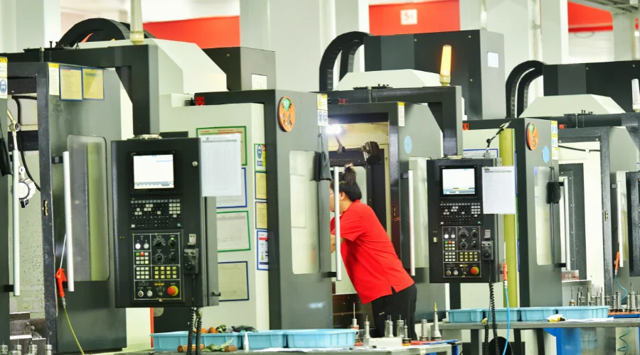
A machining center can spin a cutter rapidly, but the more revealing story takes place in a much smaller space: the contact zone between the cutting edge and the workpiece. Material is being plastically deformed, chips are separating, heat is being generated, and forces are changing continuously.
Understanding that microscopic interaction explains why some high-speed processes remain stable while others quickly develop tool wear, vibration, or surface defects.
High speed CNC machining is therefore not simply a matter of increasing spindle speed. Its behavior is governed by how the workpiece material responds to deformation, how the cutting edge transfers energy into the chip, and how the resulting heat and forces are controlled.
The Cutting Zone Is Where High-Speed Machining Is Decided
A milling cutter removes material by repeatedly entering and leaving the workpiece. Each tooth experiences changing engagement, so the cutting load is dynamic rather than constant. Research on high-speed milling identifies cutting forces as an important indicator of the interaction among the workpiece, cutter, fixturing, and machine tool.
That interaction becomes especially significant as machining conditions become more aggressive. Tool runout, cutter geometry, material properties, and engagement conditions can alter the instantaneous chip thickness from one cutting edge to another.
Consequently, engineers cannot judge a process from spindle speed alone. Two operations running at the same RPM may produce very different cutting forces because their tool diameters, engagement depths, materials, and feed conditions are different.
What Happens to the Material as Cutting Speed Rises
Cutting begins with deformation ahead of the tool edge. The cutter compresses and shears the material until a chip separates from the workpiece. The resulting chip carries away part of the mechanical energy introduced during cutting, while the remaining energy contributes to heat within the cutting system.
High-speed milling research has examined these force and chip-formation behaviors because they provide insight into machinability and tool wear. Experimental work has measured dynamic force signals across different spindle-speed ranges, demonstrating that force behavior changes with machining conditions rather than remaining a simple function of RPM.
Material response also matters considerably. Hardened steels, aluminum alloys, titanium alloys, and nickel-based alloys do not deform or transfer heat in the same way. A parameter set that works for one material cannot automatically be transferred to another.
Recent research on high-speed milling emphasizes the importance of identifying cutting-force behavior and intermediate variables such as instantaneous undeformed chip thickness and tool runout when characterizing the process.
Heat Does Not Disappear Just Because Cutting Gets Faster
Temperature is one of the most consequential variables inside the cutting zone. Mechanical work performed during material removal is converted largely into heat, with thermal energy distributed among the chip, tool, and workpiece.
The practical question is therefore not simply whether a process generates heat, but where that heat goes. A chip that carries a large proportion of the thermal energy can reduce the amount transferred into the workpiece. Conversely, unfavorable conditions can increase thermal loading on the cutting edge or substrate.
HordRT’s technical guidance similarly identifies heat management as a central concern in high-speed machining and points to cooling approaches as part of controlling thermal effects.
Material characteristics can make the problem more pronounced. Research into high-speed milling of difficult-to-machine materials such as Inconel 718 has examined cutting-force variations and dynamic effects because the machining response depends strongly on both material behavior and cutting conditions.
Tool Geometry Becomes Part of the Thermal Strategy
A cutting tool is not merely a replaceable component. Its geometry determines how the cutting edge enters the material, how chips flow away, and how much material each tooth engages during rotation.
Flute geometry, rake angle, helix characteristics, edge preparation, and tool diameter can consequently influence cutting forces and heat generation. Coatings can also be selected according to the material and operating conditions, although no coating should be treated as universally suitable for every machining situation.
Tool runout deserves particular attention in high-speed work. Even a small positional variation can cause different teeth to carry unequal portions of the cutting load. That imbalance can influence force fluctuations and accelerate localized wear. Research into high-speed milling explicitly considers tool runout when modeling cutting forces.
HordRT approaches tool selection as part of the overall machining condition rather than separating tooling from process engineering.
Surface Integrity Depends on More Than Dimensional Accuracy
A component can meet a dimensional specification while still exhibiting an undesirable machined surface. Cutting conditions influence surface texture, residual stresses, burr formation, and other aspects of surface integrity.
Free-form and precision components are particularly sensitive because the cutter may encounter continuously changing engagement conditions. Recent research describes high-speed milling as relevant to producing high-quality complex surfaces and identifies process stability as an important factor in achieving consistent results.
Surface quality also affects what happens after machining. A stable cutting process can reduce the amount of corrective finishing required, while unstable cutting may leave marks or localized defects that require additional work.
For this reason, evaluating a machining process should involve both dimensional inspection and an assessment of the finished surface against the part’s functional requirements.
Finding the Usable Machining Window
The practical objective is not maximum speed. It is a stable operating window in which cutting forces, thermal behavior, tool wear, surface quality, and dimensional performance remain acceptable for the intended part.
Engineers can establish that window by considering material, tool geometry, cutter diameter, spindle speed, feed per tooth, axial and radial engagement, cooling method, and machine dynamics together. Changing one variable can alter the balance among the others.
HordRT‘s published explanation of the process similarly emphasizes the combined role of cutting speed, feed motion, heat management, tooling, and vibration control rather than treating speed as an isolated specification.
The most useful way to understand high-speed CNC machining is therefore to look beneath the machine’s headline specifications. The real process is determined at the cutting edge, where material deformation, chip formation, heat transfer, and dynamic forces interact. Once those mechanisms are understood, higher machining speed becomes an engineering variable that can be controlled—not merely a number that can be increased.
