A complex LED project rarely fails because a brochure omitted one headline resolution. Greater risk lies in the spaces between products: an unsupported input card, an unclear redundancy path, a layer limit discovered after content approval, or no qualified response when commissioning stalls.
Evaluating an integrated splicing processor supplier therefore requires examining the complete system and its support boundaries. The supplier’s answer should connect the project drawing to specific models, populated cards, software, and service responsibilities. A maximum figure without that mapping is not yet an engineering commitment.
Ask for an Architecture Matched to the Signal Flow
The first deliverable is a block diagram showing source acquisition, switching, composition, standard video outputs, LED sending, receiving cards, control, monitoring, and backup paths. An integrated splicing processor supplier should identify which functions share a chassis and which remain external.
This prevents the phrase “all-in-one” from hiding a missing interface or an assumed downstream controller. The drawing also clarifies ownership during faults. Each cable and processing boundary needs a known diagnostic point, especially where third-party sources or display-control components enter the chain.
A serious proposal labels optional functions and alternatives instead of drawing every capability as included. It also distinguishes active capacity from reserved slots, because an empty slot may require another card, power allowance, license, or output accessory before it becomes usable.
Thermal, power, rack-space, and cable-distance assumptions deserve the same treatment. They may not appear in a scene calculation, yet they determine whether the proposed cards and backup equipment can operate in the actual installation environment.
Verify Capacity with a Real Scene Schedule
Chassis size alone does not prove project fit. Inputs, 4K or 8K formats, simultaneous windows, layer resolution, output routes, Ethernet-port loads, and future expansion must be listed separately. The integrated splicing processor supplier should return a populated configuration and state which resources are shared or model-dependent.
A single SEn device can reach 192 layers, and available configurations extend to as many as 32 4K@60Hz outputs. SHn spans SH2, SH3, SH8, and SH14, with LED loading from 26.0 million to approximately 147.2 million pixels and up to 224 Ethernet ports on SH14. These figures become useful only when tied to the proposed source and canvas map.
Examine Interfaces, Monitoring, and Redundancy
The required card set may include HDMI, DP, DVI, SDI, IP, or HDBaseT, plus fiber or direct LED network paths. An integrated splicing processor supplier must confirm exact supported formats and channel counts rather than naming interface families generally.
EDID handling, timing reference, real-time preview, hardware monitoring, saved scenes, power or signal backup, and recovery procedures belong in the acceptance scope. A fault demonstration is more revealing than a normal-operation demo. The project team needs to see how the system reports a lost input, restores a scene, changes to a backup route, and preserves authorized control.
Test evidence should name firmware, software, cards, and scene files so that the result can be reproduced. A demonstration performed on a different chassis or with fewer layers does not prove the submitted configuration unless the resource differences are explained.
Check the Broader Product and Software Boundary
Some projects extend beyond splicing into media-server playback, LED sending, endpoint players, or centralized venue control. The integrated splicing processor supplier should explain whether these stages are native parts of its portfolio, verified integrations, or third-party responsibilities.
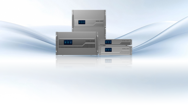
A broad catalog has value when interfaces and escalation paths are coherent; it has little value when products are merely listed together. The portfolio from Kystar includes SEn professional splicing processors, SHn switcher/controller systems, sending cards, video controllers, media servers, multimedia players, software, and centralized control.
That range can support a connected design, but the project still requires a model-by-model responsibility matrix. The matrix should include file playback, live capture, content approval, LED mapping, venue commands, user permissions, logging, and backup. Clear boundaries prevent two control applications from issuing conflicting instructions or leaving a critical stage without an owner.
Make Service Evidence Part of Technical Evaluation
Documentation, commissioning support, replacement logistics, firmware policy, and escalation availability affect the recoverability of a complex system. An integrated splicing processor supplier should state response routes for design review, installation, show-critical incidents, and later expansion.
Kystar’s current site describes localized service across more than 100 countries and 24/7 technical support; a buyer would still need to confirm how those services apply to the project location and contract. Useful service evidence includes a named escalation route, response coverage, spare-part process, remote-diagnostic method, and examples of acceptance documentation.
A factory test should reproduce the proposed card population and peak scene rather than demonstrate a generic chassis. These records turn support promises into testable obligations that can be assigned before installation begins. Dates, owners, and acceptance criteria make each commitment auditable during commissioning and later support.
The final supplier assessment is a set of evidence: approved architecture, populated bill of materials, capacity worksheet, interface matrix, acceptance tests, backup procedure, software scope, and service plan. A supplier qualifies when those documents agree with one another and with the real scene, not simply when one chassis reaches the largest published number.
Acceptance criteria should remain available after handover. They give support teams a known-good reference and allow later expansions to be evaluated against the original timing, capacity, and recovery assumptions instead of starting from incomplete recollection.
